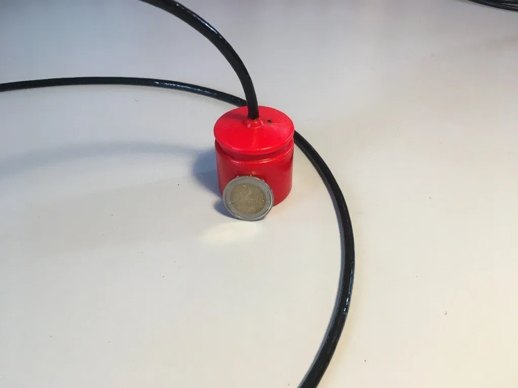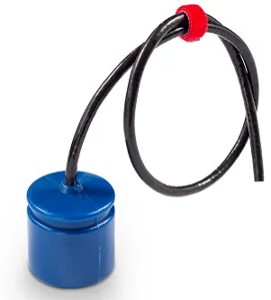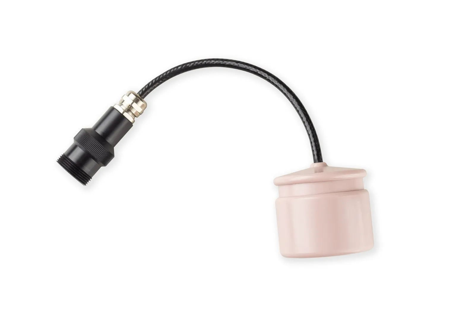
The uWave underwater acoustic modem measures 41 by 45 mm and weighs 0.16 kg, yet it talks to a host system over plain UART. That makes it easy to connect to Arduino and other microcontrollers: you need four or five wires and a library that parses the modem's text protocol. Below: what you need, how to wire the modem, how to get the uWAVE_ALib library and what it can do.
What you need
- A uWave or uWave Max modem. Modems of the uWave family share the same interface: UART at 9600 bit/s and the NMEA 0183 PUWV protocol. Other data transmission devices are listed in the Data transmission category.
- An Arduino Uno or Nano compatible board, which is what the library's examples list as the hardware.
- A 5–12 V power supply for the modem.
- A second modem, if you want to request data from a remote node or send packets.
How the modem talks to the microcontroller
The physical interface is UART with 3.3 V data lines. The default settings are 9600 bit/s, 8 data bits, 1 stop bit, no parity and no hardware flow control. The modem exchanges text NMEA 0183 sentences such as $PUWV0,1,0*hh with a checksum. Without repeaters or interface converters, correct operation is guaranteed for a cable up to 2 m long.
The modem has two modes, and the difference matters:
- Transparent channel is available right after power-on: whatever you write to the UART is sent into the hydroacoustic channel without any analysis and comes out unchanged on the receiving modem. All you need to do is connect the modem to a serial port.
- Command mode: the modem parses its input as commands. You need it for configuration, for coded requests to remote modems (depth, temperature, supply voltage) with signal propagation time measurement, and for packet mode with guaranteed delivery. It is switched on by a level on the Service/CMD wire; in the library's examples that wire is driven by an Arduino pin.
Two warnings from the documentation. The Service/CMD wire may only be pulled to a 3–5 V level or to ground: a higher voltage causes irreparable damage that is not covered by warranty. And before power is applied, this wire must be pulled to ground, otherwise the modem enters software update mode.
Wiring
The uWave cable comes in two versions that differ in wire colors: check which one you have against the wiring diagram in the documentation. The wire functions are the same. This is how they connect to an Arduino Nano in the library's examples:
| Function | Cable version 1 | Cable version 2 | Arduino Nano pin |
|---|---|---|---|
| Power +5…+12 V | green | red | VIN |
| Modem UART Tx | black | green | D2 |
| Modem UART Rx | white or transparent | white or transparent | D3 |
| Service / CMD | brown | yellow | D4 |
| GND | shield | shield | GND |
The modem's Tx goes to the receive pin of the software serial port (D2), and the modem's Rx goes to its transmit pin (D3). The modem is accessed through SoftwareSerial, which leaves the hardware Serial free for the serial monitor. The uWave Max has the same interface (UART at 9600 bit/s, NMEA 0183 PUWV, 5–12 V supply), but check the wire colors for your model against its documentation.
A word on power and logic levels. In the examples, both the Arduino and the modem are powered from the computer's USB port. In transmit mode the uWave draws 6 W (the uWave Max, 15 W) against 0.33 W when receiving, and the uWave Max reaches its maximum output power only at 12 V. Also, the modem's data lines work at 3.3 V, while the Nano runs at 5 V. The examples do not describe level matching, so for a permanent installation arrange it yourself: use a 3.3 V board or a level shifter.
Installing the library
The uWAVE_ALib library is open source under the GPL-3.0 license. The source code is on GitHub, with a mirror on GitVerse. The repository has no releases and no library.properties file, and the library is not in the Arduino IDE Library Manager index, so it is installed manually:
- Download the repository (Code → Download ZIP) or clone it.
- Create a new sketch and copy two files from the
srcdirectory into the sketch folder:uWAVE_ALib.handuWAVE_ALib.cpp. - In the sketch, include
SoftwareSerial.hand"uWAVE_ALib.h".
The examples directory contains two ready-made sketches. Before running any code, check that the modem responds: connect it to a computer through a UART-USB converter, switch on command mode and send the device information request $PUWV?,0*27 ending with CR LF. This example is given in the protocol specification.
Example: requesting data from a remote modem
The first example in the repository (“all in one”) demonstrates almost all the basic techniques and prints requests and results to the serial monitor. Below is a fragment abridged and simplified from it: comments, the initial setup and the handling of the other events have been removed. Source: examples/uWAVE_ALib_example_1.ino, github.com/ucnl/uWAVE_ALib, GPL-3.0 license.
#include <SoftwareSerial.h>
#include "uWAVE_ALib.h"

#define SPEED_OF_SOUND (1500)

#define REMOTE_MODEM_TX_ID (0)
#define REMOTE_MODEM_RX_ID (0)
#define REMOTE_REQUEST_PERIOD_MS (5000)

#define uWAVE_RX_PIN  (3)
#define uWAVE_TX_PIN  (2)
#define uWAVE_CMD_PIN (4)

long rem_req_ts = 0;

SoftwareSerial uWavePort(uWAVE_TX_PIN, uWAVE_RX_PIN);

uWAVE uWrapper(&uWavePort, uWAVE_CMD_PIN);
uWAVE_EVENT_Enum result;

void setup()
{
  uWavePort.begin(9600);
  Serial.begin(9600);

  uWrapper.enable();
}

void loop()
{
  result = uWrapper.process();

  if (result != uWAVE_NONE)
  {
    if (result & uWAVE_REMOTE_RESPONSE_RECEIVED)
    {
      Serial.print(F("propagation time, s="));
      Serial.println(uWrapper.getRem_propTime_s());
      Serial.print(F("Slant range, m="));
      Serial.println(uWrapper.getRem_propTime_s() * SPEED_OF_SOUND);
      Serial.print(F("value="));
      Serial.println(uWrapper.getRem_value());
    }
  }
  else if (!uWrapper.isWaitingLocal() && !uWrapper.isWaitingRemote() &&
           (millis() - rem_req_ts >= REMOTE_REQUEST_PERIOD_MS))
  {
    if (uWrapper.queryRemoteModem(REMOTE_MODEM_TX_ID, REMOTE_MODEM_RX_ID, RC_DPT_GET))
      rem_req_ts = millis();
  }
}
How it works:
enable()raises the level on the CMD wire, which switches command mode on.process()should be called as often as possible. It reads the port and returns a set of event flags: an acknowledgement, a remote response, a timeout, a delivered packet and so on.queryRemoteModem()sends a coded request to the remote modem rather than returning data right away. The response arrives as auWAVE_REMOTE_RESPONSE_RECEIVEDevent with the signal propagation time and the requested value. ForRC_DPT_GET, that value is the remote modem's depth. Only one request runs at a time, which is why the condition checksisWaitingLocal()andisWaitingRemote().- Slant range is the propagation time multiplied by the speed of sound. The example uses 1500 m/s. A time resolution of 0.0001 s gives 0.15 m of range resolution at that speed, but the real speed of sound depends on temperature, salinity and depth. There is an online calculator for the speed of sound; the same page has an NMEA 0183 checksum calculator, handy for manual debugging.
Typical tasks
Telemetry and ranging. The RC_DPT_GET, RC_TMP_GET and RC_BAT_V_GET requests return the remote modem's depth, temperature and supply voltage, and the response time gives the distance to it. A modem with a pressure/temperature sensor reports its own readings once configured with queryForAmbientDataConfig(): depth, pressure, water temperature and supply voltage, either once or at an interval from 0.5 to 60 s.
Remote control. The modem has nine user coded commands, RC_USR_CMD_000 … RC_USR_CMD_008. The second example in the repository maps them to nine Arduino pins (D5–D13): when a command is received, the corresponding pin goes high for 500 ms. You can connect LEDs through a 200–300 ohm resistor, or relays. That lets you control an autonomous underwater device without a cable.
Packet data transfer. In packet mode the modem sends up to 64 bytes with guaranteed delivery (ALO, at-least-once) and delivery notification. Addresses run from 0 to 254, and address 255 is used for broadcast messages without acknowledgement. In the library, queryForPktSend() sends a packet, and the outcome arrives as uWAVE_PKT_DELIVERED events with the number of attempts, uWAVE_PKT_SEND_FAILED and uWAVE_PKT_RECEIVED with the sender's address. To work in this mode the modems are switched to command mode; see the protocol specification for details.
Transparent channel. If all you need is to move bytes, you do not need the library: data written to the UART goes into the hydroacoustic channel as is. That is enough to link two microcontrollers.
Links
- Documentation: the protocol specification, the uWave wiring diagram, the uWave Max specification.
- The uWAVE_ALib library: GitHub, GitVerse. Older Arduino examples: uWAVE_Arduino.
- UC&NL educational projects and online utilities: diy.unavlab.com.
Need help integrating the modem into your device? Get in touch.