"The vessel's true position, though it is known, is not random — it exists, but at a point that is unknown."
Alekishin V.G. et al., Practical Seamanship, 2006, p. 71
With this article, we are launching a series about the practical use of our own navigation systems.
The very first RedNav long-baseline navigation system kit, serial number 1, was built and delivered to a customer back in the now-distant summer of 2015. Since then we have sold several dozen such kits, but even though we have had our own robot since 2017, we could not run a full trial on it until April 2019, due to being busy developing, improving, and manufacturing both existing and new devices and systems. In this article we will make up for that and describe how it works from a developer's perspective.
Problem statement
Flying, driving, crawling, and surface-swimming drones stream live video from their cameras and often GPS coordinates too, so the operator can easily tell where the vehicle is — and more often than not, the operator can simply see it directly.
With underwater vehicles (ROVs) it's a different story. Once you send the vehicle into the water, there is only one thing you can be sure of — it is definitely underwater.
A bit deeper into the problem
ROVs come in different classes, based on size and purpose. The simplest and smallest — like ours — are inspection-class vehicles: essentially a video camera on a tether, with thrusters. Larger, more sophisticated vehicles can be fitted with manipulator arms and other tools for interacting with their surroundings. Tether lengths range from tens to a couple hundred meters for small vehicles, and can reach thousands of meters for serious work-class equipment.
Classic ROV control relies on visual feedback — the operator watches the image sent from the vehicle's cameras over the tether. ROVs are often fitted with sonars as well, since visibility in the survey or work area frequently does not exceed 1–3 meters.
The biggest drawback of this approach is that the image on the monitor almost never lets you tell, with any reasonable accuracy, exactly where the vehicle actually is.
Underwater navigation
This drawback is addressed with hydroacoustic positioning systems. Typically, a pinger (a device that periodically emits a special signal) or a responder-beacon is mounted on the vehicle. The pinger's signal is used for direction-finding and ranging, and the vehicle's position is then calculated from the angle (or two angles — horizontal and vertical) of arrival and the range. Such systems are called USBL (ultra-short baseline). They belong to the angle-and-range family and have a whole list of drawbacks, especially for this particular task.
Determining the horizontal angle of arrival of the responder's or pinger's signal requires a direction-finding antenna. Older systems also had to determine the vertical angle of arrival; in newer systems, including ours, the responder-beacon transmits its own depth, which simplifies the task and improves the system's accuracy. A direction-finding antenna is a fairly complex device in its own right, and it has to be mounted on a pole fixed to the vessel. Range, depth, and horizontal angle (or range and two angles) only give the vehicle's position relative to the antenna. And accuracy drops as the range increases.
The accuracy of angle determination depends on:
- the characteristics of the antenna itself, which is usually on the order of 0.5–3°, reaching 0.03° in the most advanced systems — though that comes at a very steep price (more than €150,000). As a reminder, 1° of error at a range of 1000 meters translates into a spread of 17 meters (i.e., ±17 meters);
- how accurately the antenna's own orientation is known (roll and pitch);
- the specific hydrological conditions. For example, the antenna might pick up a reflection, or a combination of reflections, instead of the direct signal, thereby measuring the angle of arrival of a reflected signal — one that could have bounced off anything, including from a completely different direction.
Once the range and the angle of arrival are known, all of this still needs to be tied to geographic coordinates. That requires knowing the geographic position of the direction-finding antenna and the bearing of its reference zero relative to true north — in other words, you also need a compass and a GPS receiver on the antenna, i.e., a heading and positioning system. Only then can the direct geodetic problem be solved and the underwater vehicle's position expressed in geographic coordinates.
In terms of accuracy, a long-baseline system is preferable to a USBL system. We recommend using a USBL system only where a long-baseline system cannot be used — for example, when positioning a towed object that has to cover a very long distance. In that case, the long-baseline elements would have to be repositioned very often, costing too much time and effort; or, another example, when it is impossible or very difficult to deploy long-baseline buoys on the surface because of the great depth at the work site. In every other case, we recommend using the RedNav long-baseline navigation system — it is more reliable and more accurate than a USBL system.
In long-baseline (LBL) systems, the navigation base is formed by several receivers or transmitters spread out in space. The best-known examples of long-baseline navigation systems are GPS and GLONASS, though other satellite navigation systems exist too. The advantage of long-baseline hydroacoustic navigation systems is that their accuracy is essentially uniform across the entire “field” inside the base; they are much less affected by vessel motion and, overall, deliver far more accurate results than USBL systems.
In practice, we see that users tend to buy and deploy USBL systems on the assumption that a USBL system is easier to deploy than an LBL system. This stereotype exists partly because the vast majority of long-baseline systems available on the market use a so-called seabed base (the base elements are not floating, as in our RedNav, but are placed on the bottom at the work site), and deploying that kind of base takes significant time and money.
In our long-baseline system, we combine the benefits of easy deployment with the high accuracy of the resulting data.
Underwater GPS
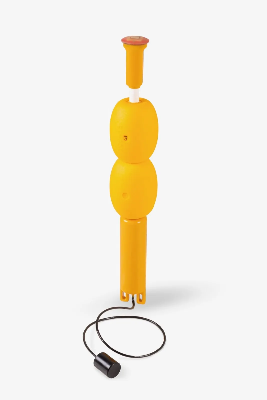
Let's get back to the star of today's trial — the RedNode system. The navigation system consists of the navigation base itself, formed by four floating buoys that relay the GNSS signal:
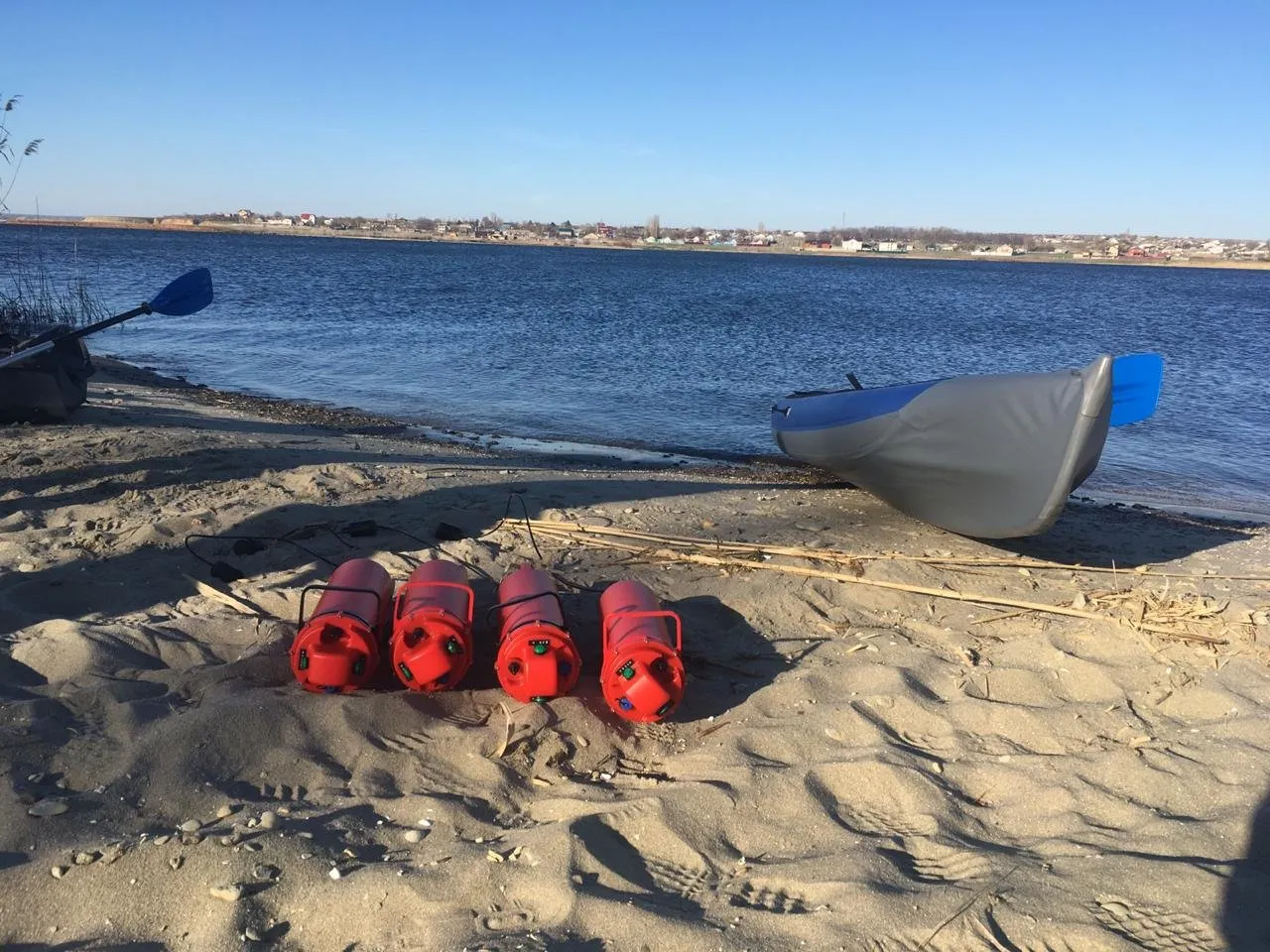
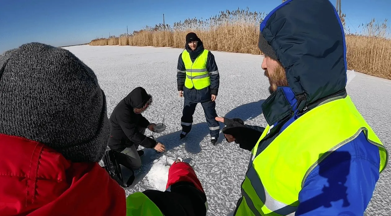
Before starting work, the buoys are deployed on the water using anchors and rope. All you need to do is switch a buoy on and lower it on its anchor line. That is really all it takes — no calibration, no preliminary synchronization, nothing — just switch it on. During our trial, our engineers deployed all the navigation system's buoys from a rowboat in under half an hour.
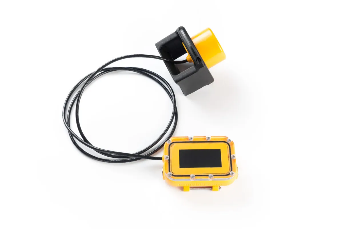
The other element of the system is the navigation receiver, mounted on the underwater object being positioned:
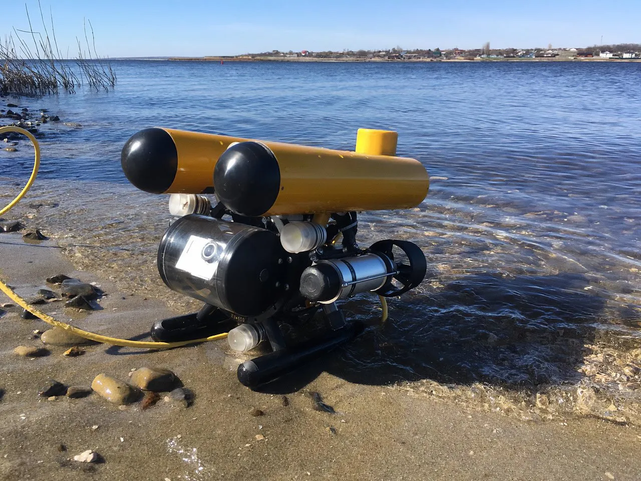
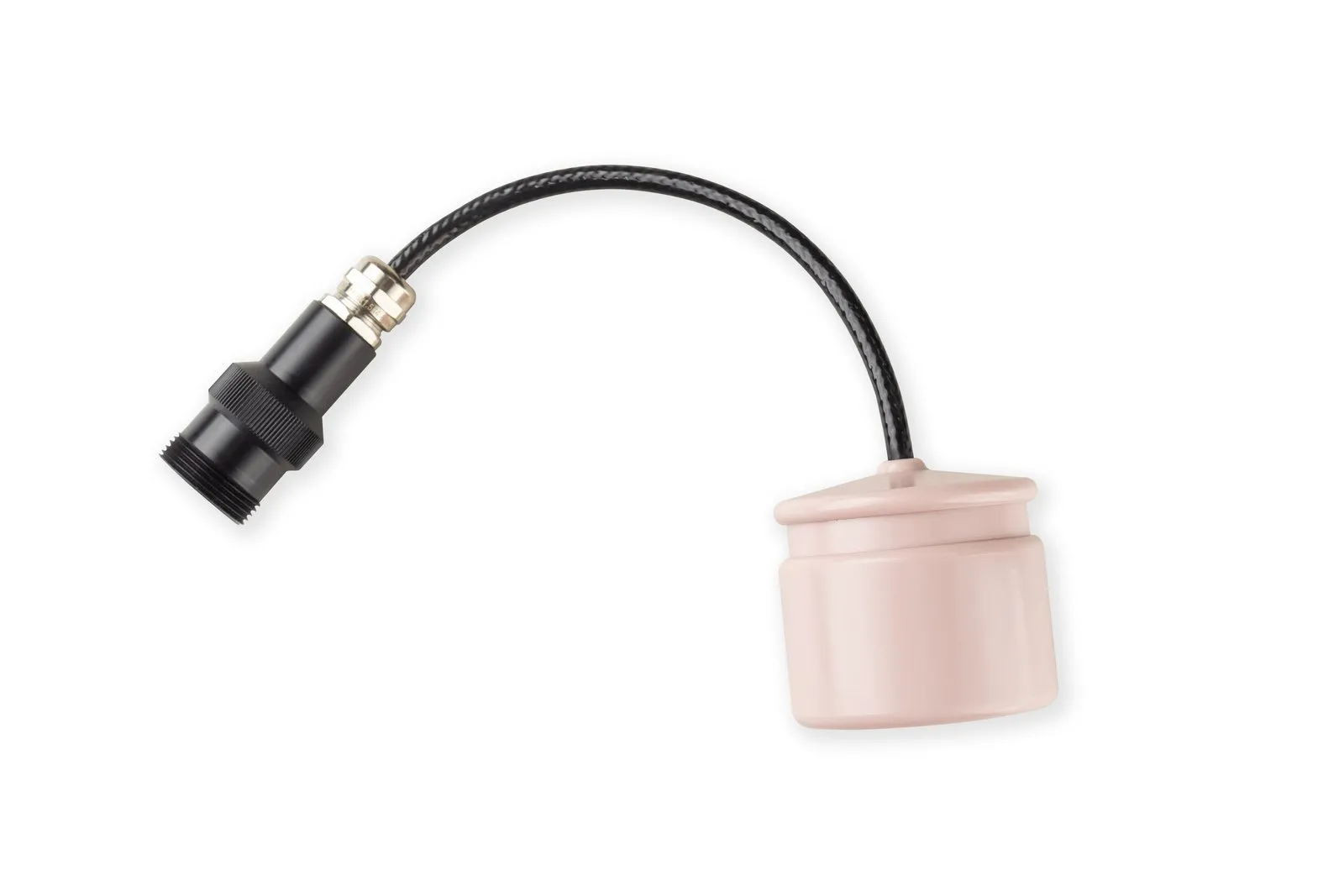
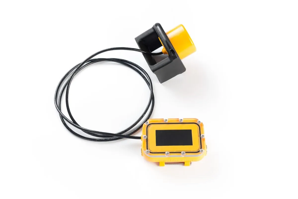
The RedNode navigation receiver (the yellow cylinder) is mounted on the stern of the vehicle. It is powered from the robot's onboard supply and sends data over the vehicle's tether.
Since the buoys only transmit and the receivers only listen (the system uses a time-difference-of-arrival scheme), a single set of buoys in one area can support any number of these receivers. That means an entire fleet of underwater vehicles and divers can navigate simultaneously, each getting its own position at a nominal rate of 1 Hz.
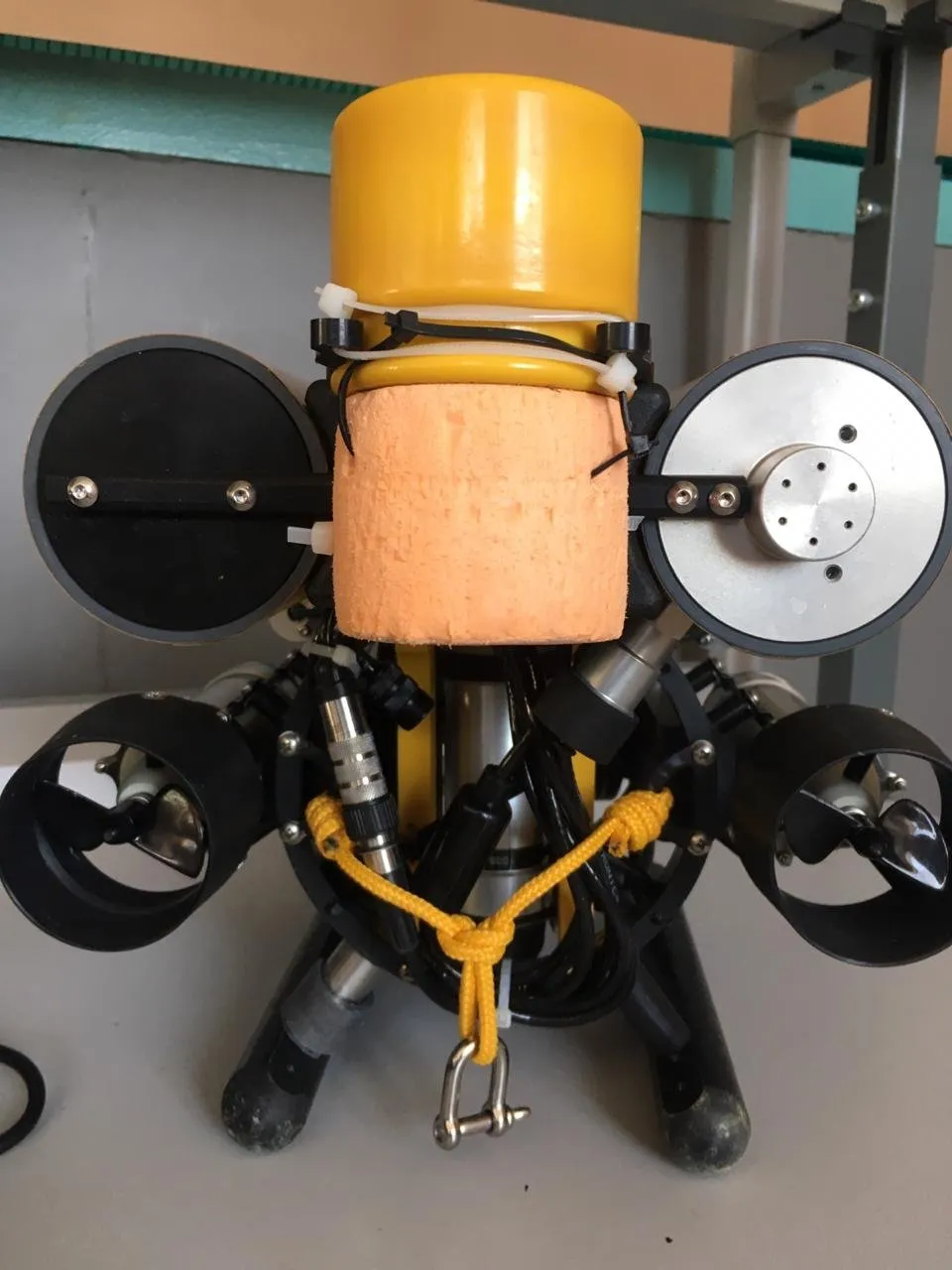
We mounted the navigation receiver in a fairly straightforward way and added a bit of buoyancy to rebalance the robot.
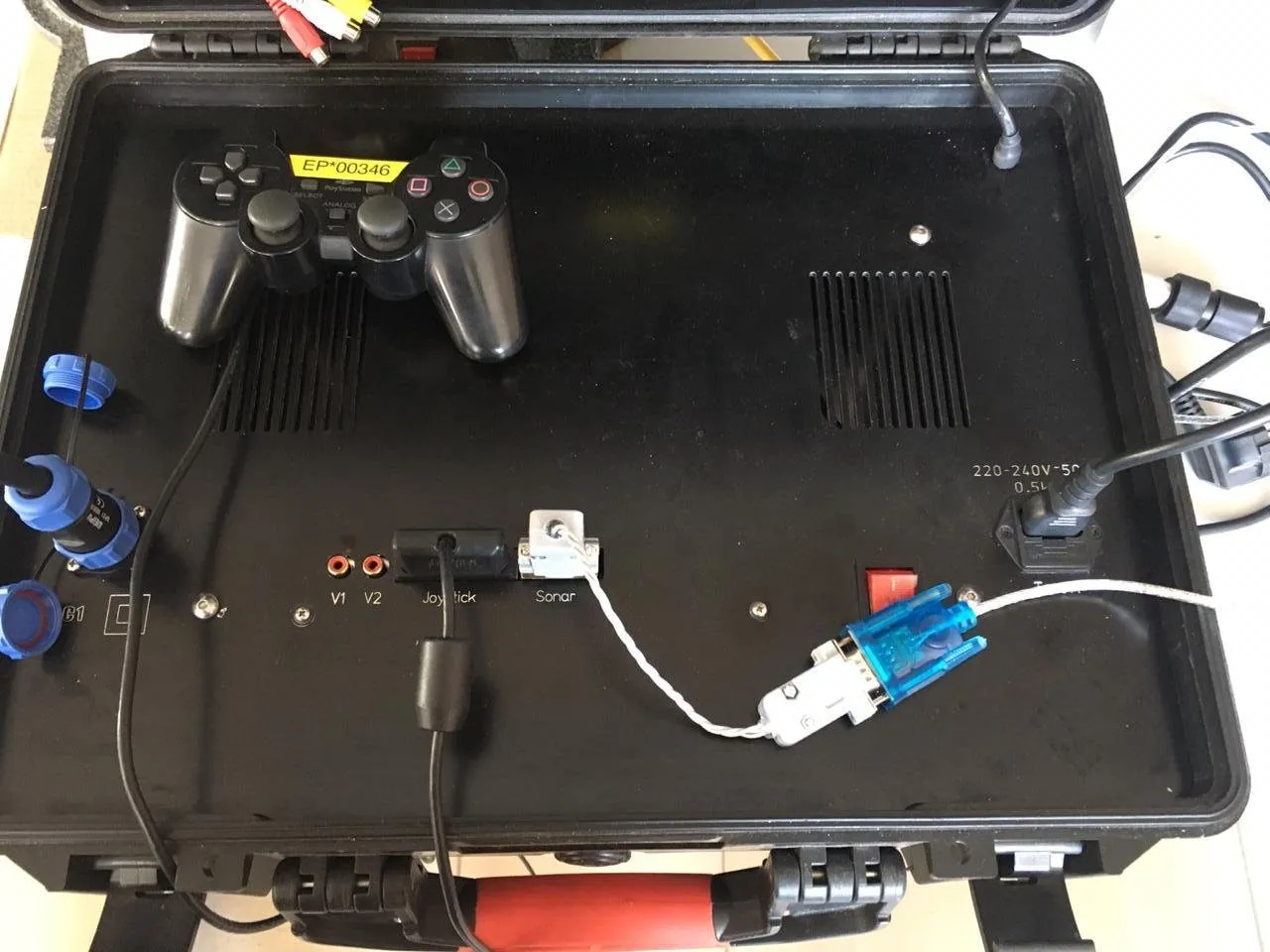
Data from the receiver goes to the control unit, from where it can be passed to any laptop through an RS232-to-USB converter (the “Sonar” connector in the photo).
In our long-baseline system, coordinates are computed on the receiver itself (so, strictly speaking, it is a navigation system, not a positioning system). But since ROVs run on a tether, there is no real problem sending the position computed on board back up the tether. The system's navigation receiver can also emulate a standard land-based GNSS receiver, which lets you connect it directly to any software that works with GNSS receivers (for example, the popular SAS.Planet application works perfectly with our navigation receiver in real time).
Going deeper
Our test setup was fairly simple:
- A ROVBUILDER RB-150 ROV with a 100-meter tether, a control unit, and a RedNode navigation receiver installed;
- A case with four RedBase buoys, plus an anchoring rig for each buoy;
- A laptop running SAS.Planet;
- An 800-watt gasoline generator;
- A two-seat inflatable kayak, the “Shuya”.
As simple as it may look, we could never have used a USBL system with this vessel — mounting a USBL antenna requires a fairly large, rigid-hulled boat (to resist rolling) and a pole rigidly fixed to the boat's side. On top of that, you would have to stay out on the water for the entire operation, which is not always comfortable or practical (low air temperature, wind, waves).
The “control post” was set up in 10 minutes, and in our case it looked like this:
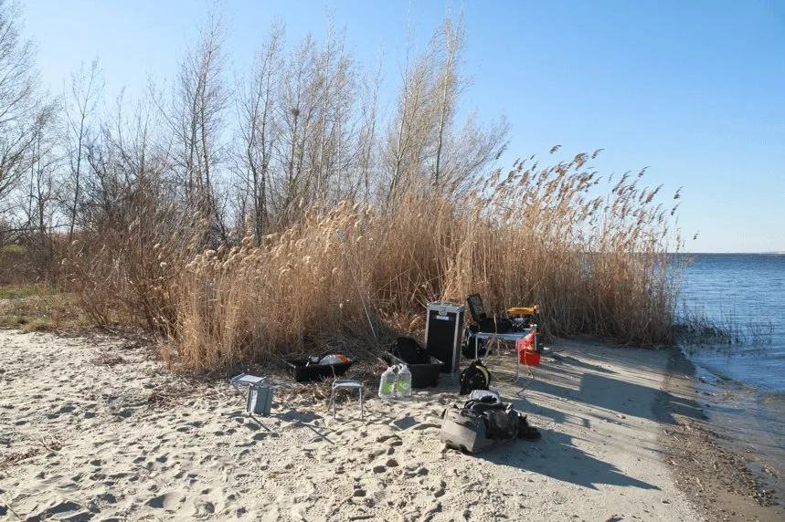
As always, we ran all of our field trials at the mouth of the Pichuga River, where it flows into the Volgograd Reservoir.
Diving in further
As mentioned above, deploying the system on the water takes no more than 30 minutes. This time, two people in a rowboat got it done in 24 minutes, rowing against the wind and chop.
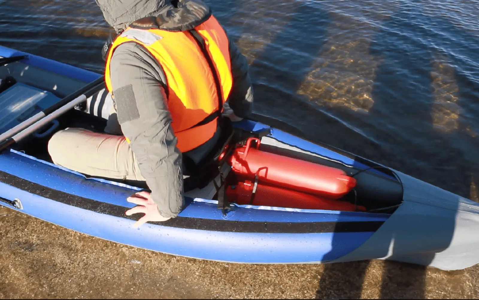
The photo shows how the buoys fit in the small inflatable kayak — all four of them.
You might assume the vehicle is also launched from the boat, but that's not strictly necessary — depending on the conditions, it can just as well be launched from shore: the vehicle is simply carried into the water:
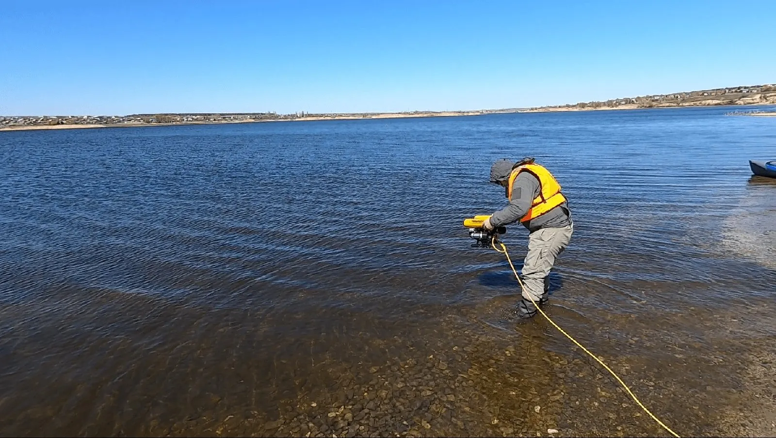
Here are the first glimpses of the underwater world:
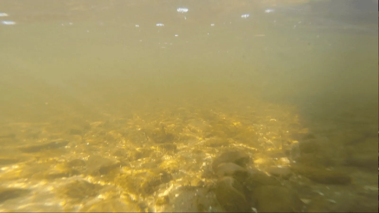
Yes, this is not the Red Sea. The water looks clear, but visibility near the shore is actually no more than 1–2 meters.
We were disappointed, but the fact remains: with such extremely poor visibility, it is simply impossible to pilot an ROV by the camera image alone.
If you'd like to judge the underwater visibility at the trial site for yourself, you can watch the recording from the vehicle's camera:
Watch the footage from the vehicle camera on YouTube
The footage is unedited and unprocessed. You can draw your own conclusions about how practical it is to control the vehicle and carry out meaningful tasks underwater — such as searching for something — using only the camera image, with no navigation data.
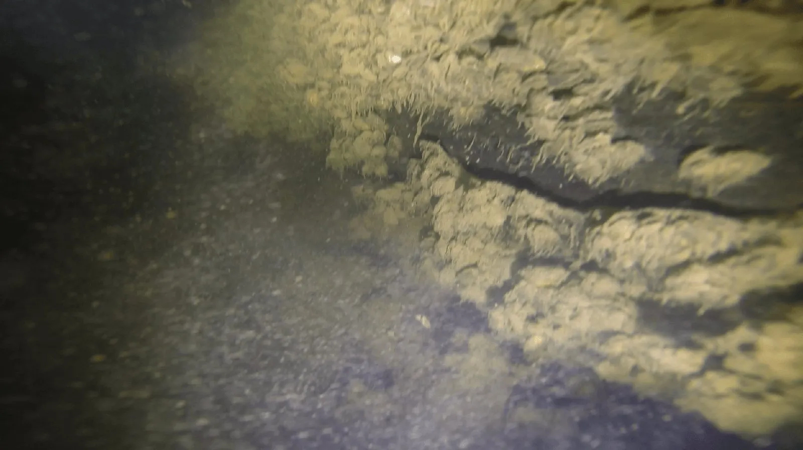
And here is the first touchdown on the bottom, with a bit of “lunar landscape” at a depth of 13 meters:
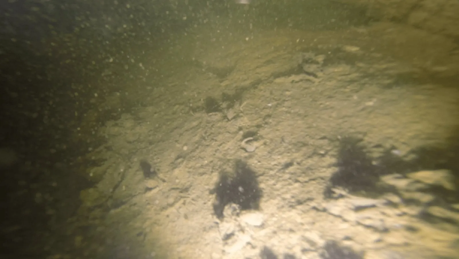
A couple of seconds later, after moving a bit farther, the vehicle bumped into a sunken log covered in small shells:
The trial scenario went as follows: an easily visible object is dropped from the boat and sunk, the drop coordinates are saved with a phone, and the operator's task is to use the navigation system's data to steer the robot to the drop site and try to visually locate the sunken object.
We concluded that it is completely impossible to control the vehicle using only the camera image; we relied mainly on our navigation system, which showed the vehicle's current position on the map online, in real time.
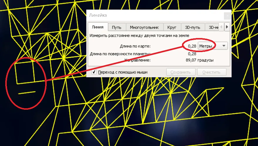
Specialists will be pleased to see the system's resolution in a real body of water, which comes out to around 30 centimeters, as shown by the grid pattern produced by the position solutions:
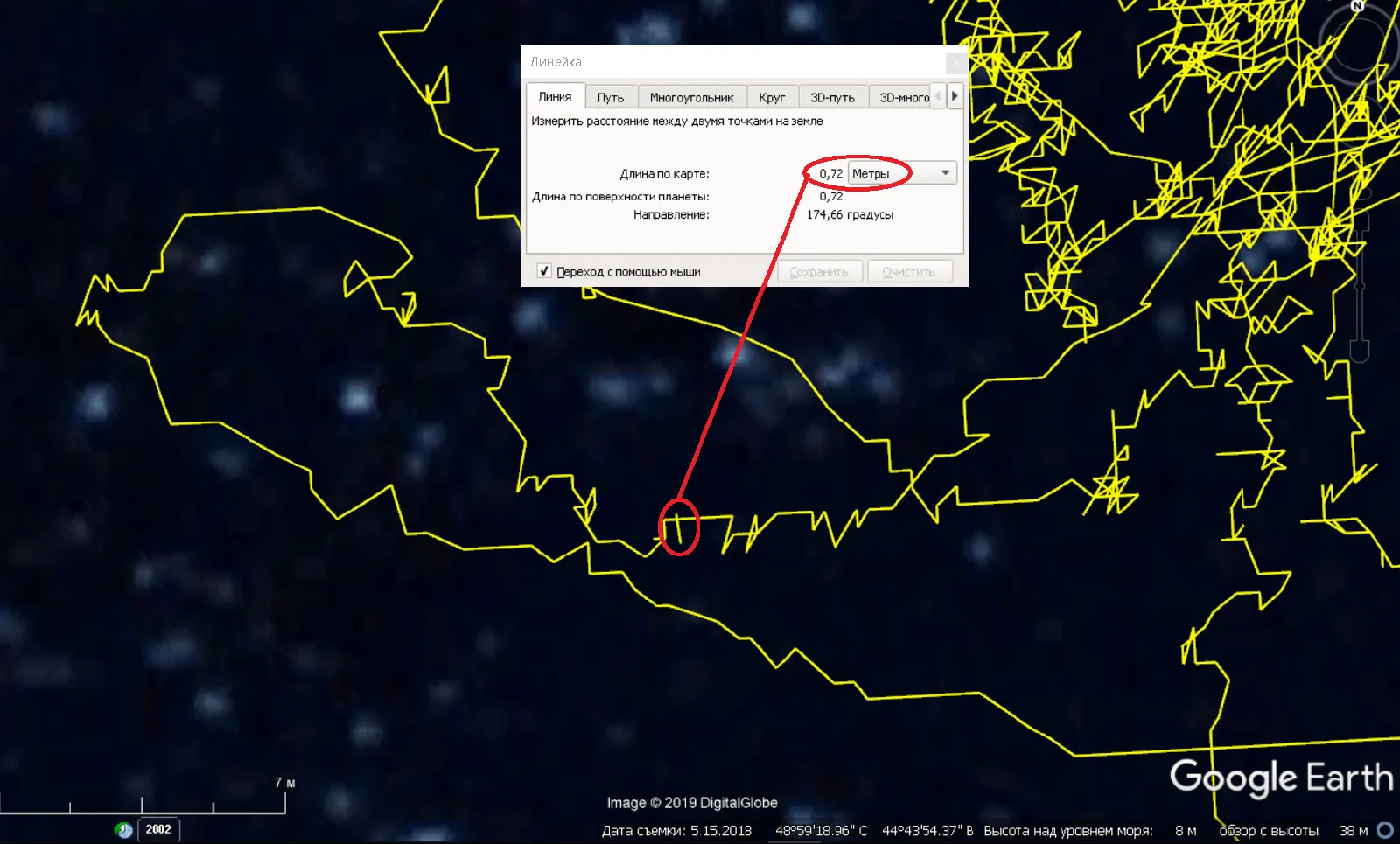
As in other similar trials, the scatter of points during movement falls within a range of 1–1.5 meters, which provides enough accuracy for most inspection tasks:
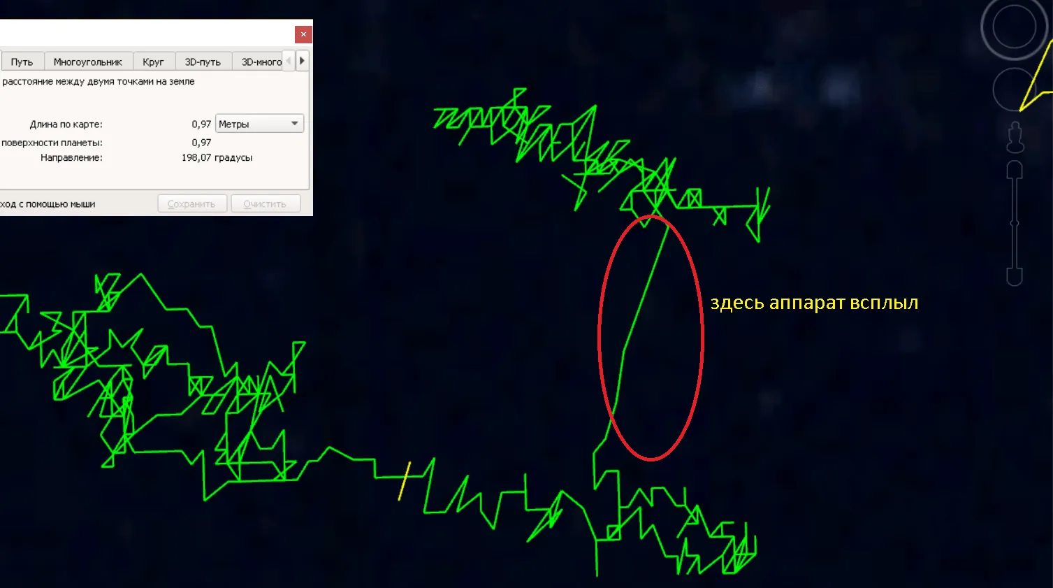
The final track of the vehicle's movement looks like this:
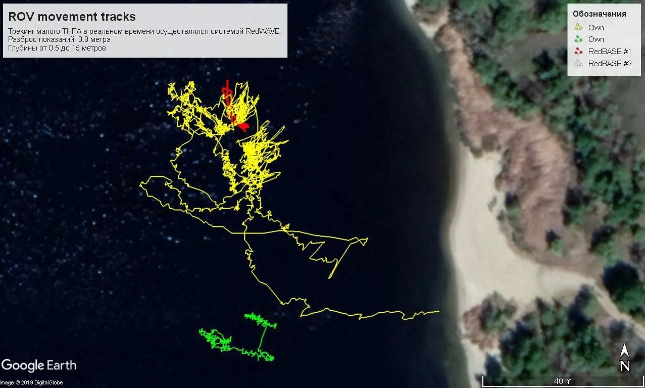
We slightly misjudged the work site, and almost half of the track (the part to the left of the red lines) lies outside the navigation base — that is, outside the buoy figure, where the system is expected to perform much worse. However, apart from a few outliers, the system performed with very high accuracy.
On one of the passes, the vehicle came very close to the assumed drop site:
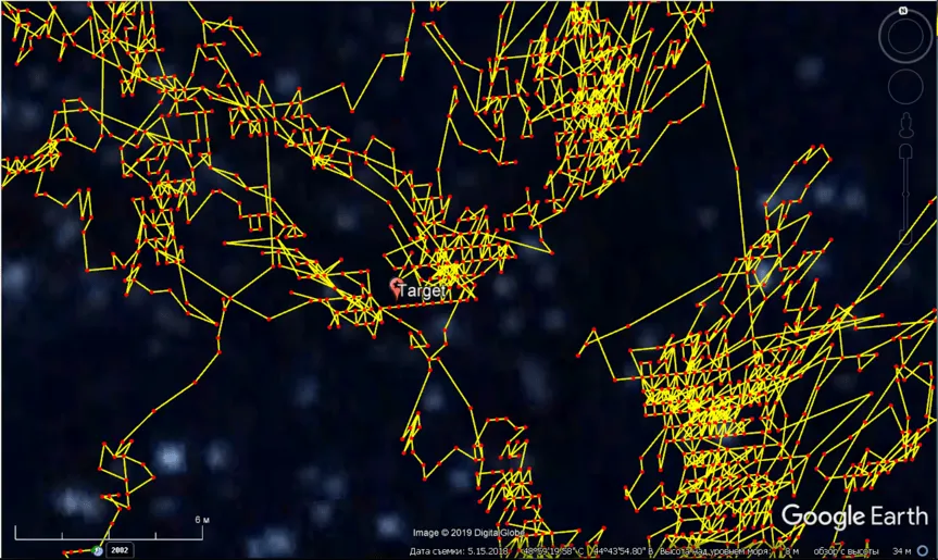
But after carefully reviewing more than an hour of footage from the vehicle's onboard camera, we never once spotted the object we were looking for — indirectly confirming our observation that no meaningful task can be accomplished relying on the video image alone.
Watch the video report from the trials on YouTube
We invite you to discuss this article! Follow the link for the tracks recorded during these trials, in KML format, for you to explore on your own.